IoThing & Arduino


IoThing is a simple board for demonstrating the capabilities of the ESP8266 WiFi device. It uses the '03' variant which has an integral ceramic antenna and also a few more I/O pins than some other variants.

The photo below shows a complete IoThing:


The board has 3 sensors:
You might be forgiven for thinking I'm obsessed wih temperature! These sensors have completely different interfaces and it's useful for students to see these.
The I2C bus is exposed, and more by chance than design, quite a few 'off the shelf' I2C modules can be plugged in directly. It might be apparent from the photo that the BMP180 and a 128x64 OLED display both use the I2C bus here.

As well as the sensors there is a 3A mains relay, a white LED, and a push-button switch. The switch & LED share the same (GPIO0) I/O pin.

Power


Power is normally provided via a mini USB socket, however +5v & GND points are available next to the USB socket for an alternative source. Note that the USB connection is purely for power.

The 5v input is followed by a LM1117 linear regulator to provide 3v3 to the circuit. The relay coil is driven from the 5v input and a NPN transistor.

Current drain is typically 100-200mA but can peak at over 300mA when the ESP8266 is transmitting.

A stable power source is easily the most common source of grief using these devices.

Installing the Arduino IDE


This is well documented esewhere so I won't repeat it here. Arduino is currently at 1.6.5 - it's better to use this or whatever the latest release is rather than 1.6.4.

Writing code


This is just like using a regular Arduino. First we need to set the IDE for the appropriate board; on the 'Tools' menu select 'Generic ESP8266 Module' as the board to use. This should be confirmed in the info line at the bottom of the IDE window:


Programming


A USB-serial adapter which works at 3v3 is necessary to connect the IoThing to your PC. These are fairly common,around £2 on ebay.
It's possible to implement 'one click' programming with the ESP8266 in the same way that a normal Arduino works but I've never had much succes with this. I prefer a more reliable approach!

The IoThing has only 3 programming connections: Tx,Rx, & GND. These must be connected to Rx,Tx, & GND respectively of the serial adapter.

A normal Arduino enters bootload mode when it is reset. The ESP8266 is slightly different - it enters bootload mode when it is reset IFF GPIO0 is low at the time of reset.

To enter the bootloader mode:
  1. Switch off the IoThing (use the blue power button)
  2. Press and hold the push-button (this grounds GPIO0)
  3. Switch on the IoThing
  4. Release the push-button

It's now in bootload mode. Hit the upload button in the Arduino IDE & your program will upload.

Programs


ESP8266 programs look like normal Arduino programs but there are a few gotchas!

Not really a 'gotcha' but you might be surprised by how big your programs are when they are compiled & uploaded. This is because we also upload the underlying WiFi stuff every time. You can see this happening if you watch the progress window carefully.

Blocking loops need a little care. With a normal Arduino we might wait for a button to be pressed like this:

while(button_not_pressed) {}        //wait here until button is pressed

This will not work with the ESP8266. The reason being that your program is sharing the CPU with the WiFi & TCP/IP stuff which needs regular access to the CPU. The code above would quite quickly cause a RESET from the inbuilt watchdog timer. Try it if you don't believe me! Thankfully this is easy to get around. Any indefinite (or long) loops should call the yield() function which passes control to the underlying network stuff. We might rewrite the line above:

while(button_not_pressed) {yield()}        //wait here until button is pressed
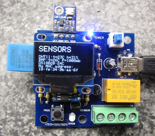
This is the 3rd most common source of grief!

Connections


Using the I/O pins on the ESP8266 is just like using pins on an Arduino. As discussed already, some have special functions which we must be wary of. It's also possible to 'remap' many of the pins but that's beyond the scope of this discussion.

The IoThing has several devices on board which are hard wired & commit certain pins to certain operations:

Pin number
Function
GPIO0
Button, white led, & boot mode
GPIO2
DS18B20
GPIO12
SCL
GPIO13
SDA
GPIO14
DHT11
GPIO16
Relay

GPIO0 is wired such that the push button grounds the pin when pressed, enabling boot mode on reset. The white LED has its anode driven by GPIO0. A consequence of this arrangement is that the white LED will extinguish whenever the push button is pressed.

Code samples


There follows a few code samples which vary in complexity and demonstrate use of the IoThing.

Some of the most basic Arduino examples are useful to establish that we can communicate with, and effectively program the ESP8266. For example:


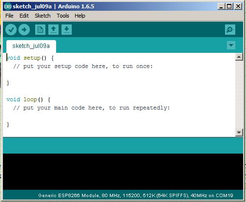
/*  Blink revisited */

#define LED 0   //LED is conneceted to GPIO0

boolean LEDSTATE=0;

// the setup function runs once when you press reset or power the board
void setup() {
 // initialize digital pin as an output.
 pinMode(LED, OUTPUT);
}

// the loop function runs over and over again forever
void loop() {
 digitalWrite(LED, LEDSTATE);   // LED on/off
 delay(1000);              // wait for a second
 LEDSTATE^=1;              //toggle the state
 
}

When successfully loaded this program should flash the white LED on & off.


Ian Sexton 2015